Overview
 System Block Diagram
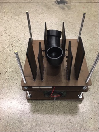
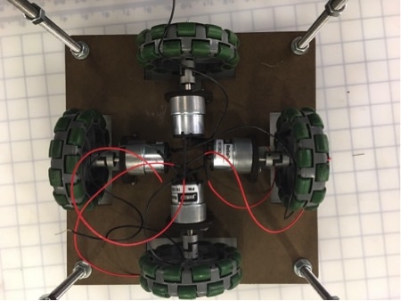
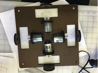
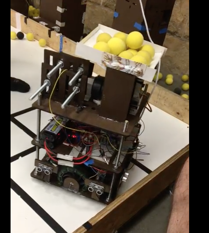
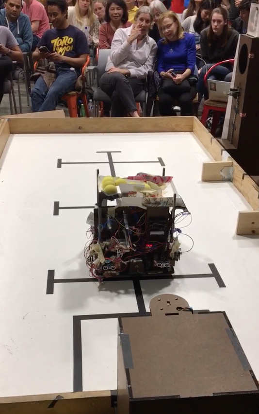
Our robot’s frame consists of two horizontal duron layers supported by four threaded studs (one in each corner). The bottom layer supports four omni-wheels, each of which is driven by a DC motor (Jameco ReliaPro 161382), connected with a set of couplers. We decided to use omni-wheels to allow the robot to easily rotate about its center axis to align itself within the playing field and to provide high precision for motor control.
Our navigational system comprises four ultrasonic sensors (HC-SR04), a pair of which are mounted on two adjacent sides of the robot, about four inches above the ground. These sensors alone allow the robot to orient itself and move about the playing field (we decided not to use tape sensors or other IR frequency sensors). We use the two sensors on each side to align the robot with respect to the walls of the playing area by reading in values from both sensors and rotating the robot until it is aligned.
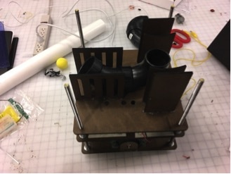
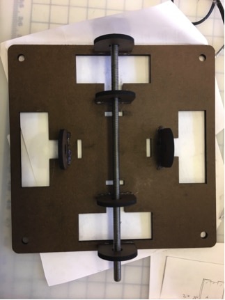
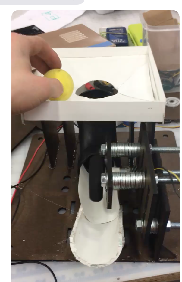
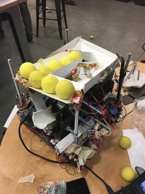
The launching system we employ to shoot the Alternative Facts comprises a hopper with a ramp to load the nerf balls into, a motor to agitate the hopper, a servo motor that rotates to open and close the opening at the base of the hopper, a curved half-pipe to transport the balls out of the hopper, a flywheel connected to a DC motor, and a duron support system for these elements.
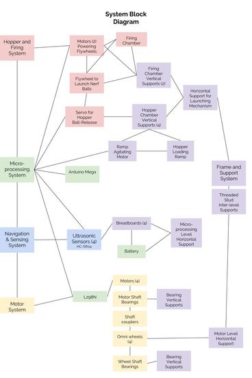
To the right is a System Block Diagram of our robot.
Our navigational system comprises four ultrasonic sensors (HC-SR04), a pair of which are mounted on two adjacent sides of the robot, about four inches above the ground. These sensors alone allow the robot to orient itself and move about the playing field (we decided not to use tape sensors or other IR frequency sensors). We use the two sensors on each side to align the robot with respect to the walls of the playing area by reading in values from both sensors and rotating the robot until it is aligned.
The launching system we employ to shoot the Alternative Facts comprises a hopper with a ramp to load the nerf balls into, a motor to agitate the hopper, a servo motor that rotates to open and close the opening at the base of the hopper, a curved half-pipe to transport the balls out of the hopper, a flywheel connected to a DC motor, and a duron support system for these elements.
To the right is a System Block Diagram of our robot.
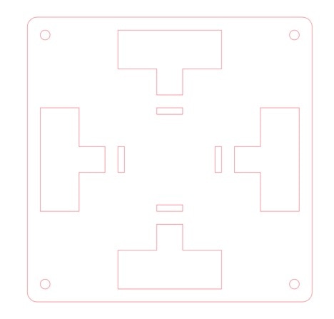
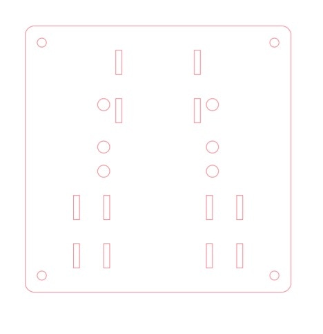
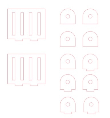
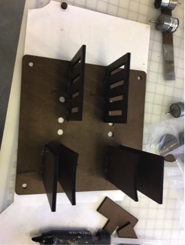
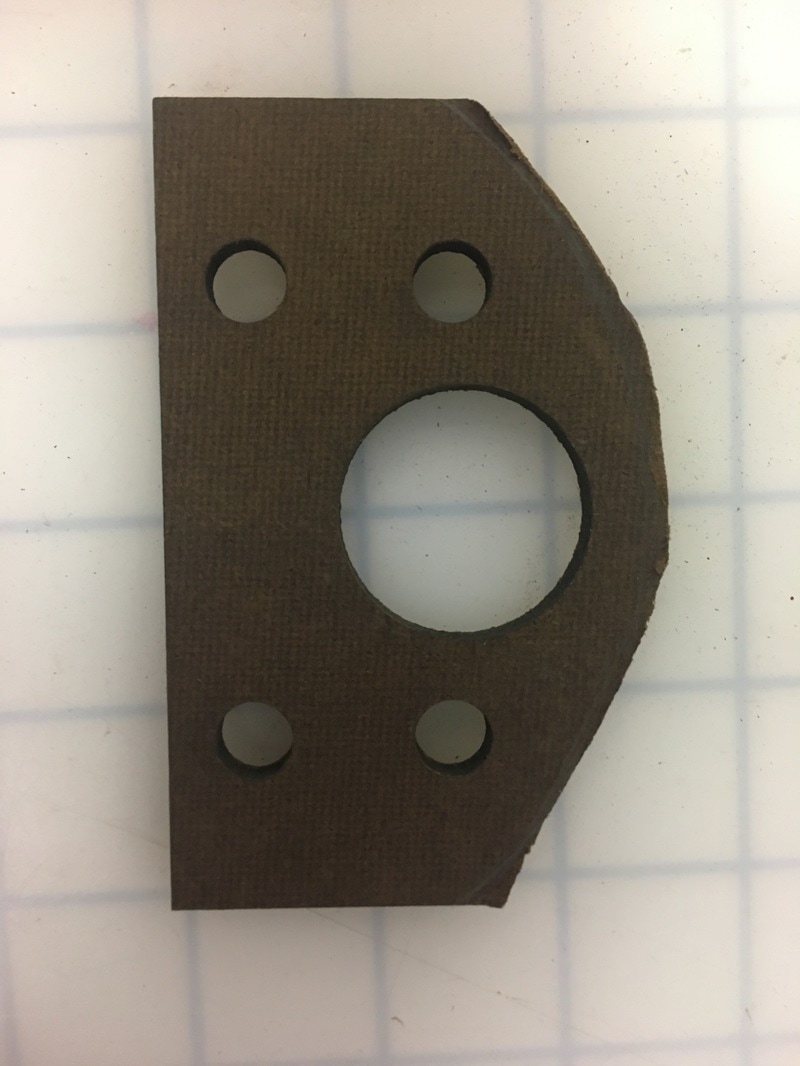
Laser Cut Parts
In addition to the Illustrator files below, we laser cut several triangular gussets for additional support.